Purpose
Provide a program that tests the control of external devices through the output commands of the U401⁄U421⁄U451.
Description
This program initializes all of the sixteen i⁄o lines of the U4x1 to be outputs and allow control of each line.
There are two ways to change the state of the output lines. The output lines can be written to as an 8-bit wide byte, and as individual bits.
The buttons labeled “Write Output” will write the byte-wide value entered in the adjacent box to the port. The left button writes to port A and the right button writes to port B.
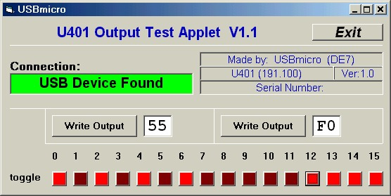
Individual lines can be controlled by toggling the buttons located below the line number at the bottom of the application window. A bright red color indicates that the line is set high, while a dark red color shows that the line is set low.
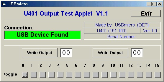
Screen Shot
Below is the application screen as it looks when the program is first initialized. Both ports (all of the lines) have been set to be outputs and have been set to all zeros. When new values are written to the ports, the individual boxes (for each line) will change from gray to either bright or dark red.
Here the application screen shows values written to the ports.
Hardware
No hardware is necessary to run this application. A volt-reading meter, such as a DVM can be used to read the status of any one of the 16 outputs. The meter ground (black) lead should be connected to the U4x1 ground connection as a reference.
A relay board such as the DT205 SimmStick can be attached to the U4x1 and controlled by this application.
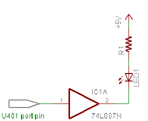
Example output circuit for driving an LED:
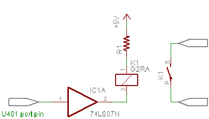
Example output circuit for driving a relay to control higher power circuits:
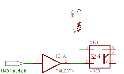
An example of an optoisolated interface:
Also, see the Relay Tutorial.