Purpose
Provide a program that initializes and writes information to an LCD.
Description
This program initializes all of the I⁄O lines of the U4x1 that are used with the LCD.
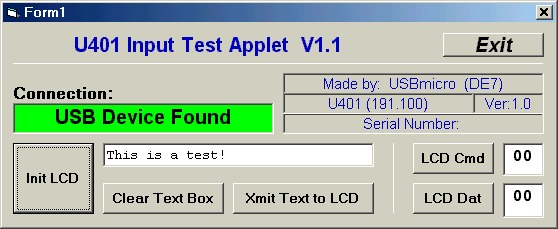
Screen Shot
The application will initialize the LCD display with a series of commands when the Init LCD button is pressed. The application can write individual LCD commands and single bytes of display data.
If text is entered into the text box, the application will copy that text to the LCD.
Hardware
The U4x1 has been interfaced to 1X16, 2X16, 2X40 (and etc.) displays. The flexibility of the commands for using any port for data and any pins for the “E”, “R⁄W”, and “RS” lines help to interface to any HD44780 device.
Example LCD connection to U4x1:
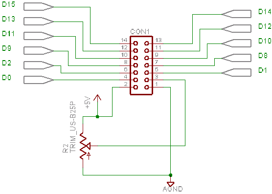
For the schematic above, use command #10 (InitLCD) to select the right port and pins. The raw command 10-10-12-00-00-00-00-00 will select port B for the data lines to the LCD, D1 for the RW line, D0 for the RS line, and D2 for the E line.
HD-44780 LCD Information
This app note describes the commands that control an HD-44780-based LCD display.
LCD Commands
| b7 | b6 | b5 | b4 | b3 | b2 | b1 | b0 | Description |
| 0 | 0 | 0 | 0 | 0 | 0 | 0 | 1 | Clear the display. Set address to 0. |
| 0 | 0 | 0 | 0 | 0 | 0 | 1 | – | Return to home position. |
| 0 | 0 | 0 | 0 | 0 | 1 | d | s | Entry mode. d = 0 (positive direction), 1 (negative direction) s = 0 (no shift), 1 (shift) |
| 0 | 0 | 0 | 0 | 1 | d | b | c | Display⁄cursor enable d = 0 (display off), 1 (display on) b = 0 (blink off), 1 (blink on) c = 0 (cursor off), 1 (cursor on) |
| 0 | 0 | 0 | 1 | s | r | – | – | Display⁄ cursor shift s = 0 (cursor shift only), 1 (display and cursor shift) r = 0 (right), 1 (left) |
| 0 | 0 | 1 | d | n | f | – | – | Data interface d = 0 (8 bit), 1 (4 bit) n = 1 (2 lines), 0 (1 line) f = 1 (5*10 dots), 0 (5*8 dots) |
| 1 | a | a | a | a | a | a | Set CG RAM address | |
| 1 | a | a | a | a | a | a | a | Set DD RAM address |
Instruction Description (From Hitachi)
Clear Display
Clear display writes space code 20H (character pattern for character code 20H must be a blank pattern) into all DDRAM addresses. It then sets DDRAM address 0 into the address counter and returns the display to its original status if it was shifted. In other words, the display disappears and the cursor or blinking goes to the left edge of the display (in the first line if 2 lines are displayed). It also sets I⁄D to 1 (increment mode) in entry mode. S of entry mode does not change.
Return Home
Return home sets DDRAM address 0 into the address counter and returns the display to its original status if it was shifted. The DDRAM contents do not change. The cursor or blinking go to the left edge of the display (in the first line if 2 lines are displayed).
Entry Mode Set
I⁄D: Increments (I⁄D = 1) or decrements (I⁄D = 0) the DDRAM address by 1 when a character code is written into or read from DDRAM. The cursor or blinking moves to the right when incremented by 1 and to the left when decremented by 1. The same applies to writing and reading of CGRAM.
S: Shifts the entire display either to the right (I⁄D = 0) or to the left (I⁄D = 1) when S is 1. The display does not shift if S is 0. If S is 1, it will seem as if the cursor does not move but the display does. The display does not shift when reading from DDRAM. Also, writing into or reading out from CGRAM does not shift the display.
Display On⁄Off Control
D: The display is on when D is 1 and off when D is 0. When off, the display data remains in DDRAM, but can be displayed instantly by setting D to 1.
C: The cursor is displayed when C is 1 and not displayed when C is 0. Even if the cursor disappears, the function of I⁄D or other specifications will not change during display data write. The cursor is displayed using 5 dots in the 8th line for 5 ´ 8 dot character font selection and in the 11th line for the 5 ´ 10 dot character font selection (Figure 13).
B: The character indicated by the cursor blinks when B is 1 (Figure 13). The blinking is displayed as switching between all blank dots and displayed characters at a speed of 409.6-ms intervals when fcp or fOSC is 250 kHz. The cursor and blinking can be set to display simultaneously. (The blinking frequency changes according to fOSC or the reciprocal of fcp. For example, when fcp is 270 kHz, 409.6 ´ 250⁄270 = 379.2 ms.)
Cursor or Display Shift
Cursor or display shift shifts the cursor position or display to the right or left without writing or reading display data (Table 7). This function is used to correct or search the display. In a 2-line display, the cursor moves to the second line when it passes the 40th digit of the first line. Note that the first and second line displays will shift at the same time. When the displayed data is shifted repeatedly each line moves only horizontally. The second line display does not shift into the first line position. The address counter (AC) contents will not change if the only action performed is a display shift.
Function Set
DL: Sets the interface data length. Data is sent or received in 8-bit lengths (DB7 to DB0) when DL is 1, and in 4-bit lengths (DB7 to DB4) when DL is 0.When 4-bit length is selected, data must be sent or received twice.
N: Sets the number of display lines.
F: Sets the character font.
Note: Perform the function at the head of the program before executing any instructions (except for the read busy flag and address instruction). From this point, the function set instruction cannot be executed unless the interface data length is changed.
Set CGRAM Address
Set CGRAM address sets the CGRAM address binary AAAAAA into the address counter. Data is then written to or read from the MPU for CGRAM.