VERSION 1.20+ of the firmware, VERSION 34+ of the DLL
Purpose
Provide a program that tests the control of a stepper motor through the commands of the U401⁄U421⁄U451.
Description
This program initializes all of the sixteen i⁄o lines of the U4x1 to be outputs. The lower four port pins of port A (A.0 – A.3) are “channel 1” when it concerns stepper activity, the upper four port pins of port A (A.4 – A.7) are “channel 2” when it concerns stepper activity.
Screen Shot
Below is the application screen as it looks when the program is first initialized. Both ports (all of the lines) have been set to be outputs.
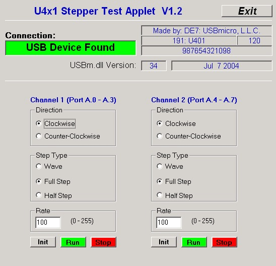
“Direction” sets the direction that the stepper motor moves. The actual direction does depend on the stepper motor wiring. The rate is the period in 128-microsecond increments, “100” in the example is 12.8 ms between each step.
The “Init” command will pass the initial step value to the motor. This is the first positional value. While the motor is running, the direction can be changed and the rate changed.
The Step Types are as follows:
Wave step
| Step | A.7 ⁄ A.3 | A.6 ⁄ A.2 | A.5 ⁄ A.1 | A.4 ⁄ A.0 |
| 1 | ON | |||
| 2 | ON | |||
| 3 | ON | |||
| 4 | ON |
Full step
| Step | A.7 ⁄ A.3 | A.6 ⁄ A.2 | A.5 ⁄ A.1 | A.4 ⁄ A.0 |
| 1 | ON | ON | ||
| 2 | ON | ON | ||
| 3 | ON | ON | ||
| 4 | ON | ON |
Half step
| Step | A.7 ⁄ A.3 | A.6 ⁄ A.2 | A.5 ⁄ A.1 | A.4 ⁄ A.0 |
| 1 | ON | |||
| 2 | ON | ON | ||
| 3 | ON | |||
| 4 | ON | ON | ||
| 5 | ON | |||
| 6 | ON | ON | ||
| 7 | ON | |||
| 8 | ON | ON |
Hardware
Below is a simplified schematic to run one of the windings of the stepper motor. The specifics of the driver circuit depend on your stepper motor.
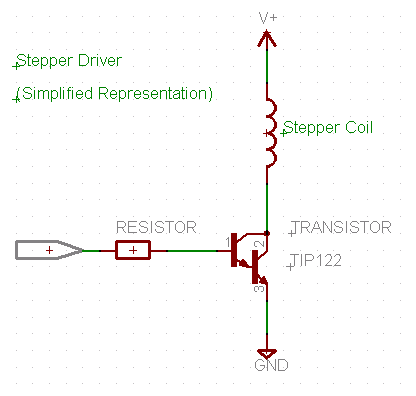
NEVER connect the stepper motor directly to the U4x1 device, a driver circuit is required!
Code