Why does the strobe function only strobe correctly after the first use?
The strobe byte write places a byte at a port (either A or B) and then toggles a single line on the other port. If set up to strobe the line “negative”, the line will be set low, then high. If the line is not initially set high, the strobe will not function correctly the first time.
The strobe function doesn’t set the initial state of the line. If you wish to have that line strobe from high to low and back to high (“negative”), then set the initial state of the line to high. The strobe function returns the line high when done.
If you wish to have that line strobe from low to high and back to low (“positive”), then set the initial state of the line to low. The strobe function returns the line low when done.
One or more of the bits that I forced to 0 in the “AND term” of the bit writing command are set. Why did this happen?
Look at your OR term. The AND term is performed first but is modified by the OR term. As an example, the command 03-00-01-00-00-00-00-00 will set the lowest bit despite the AND term wanting to turn it off.
If you use the USBm DLL the function call would be “WriteABit(device, 0x00, 0x01)”.
I’m trying to write to the LCD, but the lines RW, RS, and E and the data port never change. What is wrong?
The LCD commands do not set the direction of the lines. Use the direction command to set these lines to outputs.
I’m getting the message “apigid32.dll not found” on a Windows PC. What is wrong?
Take a look at the U4x1 Programming Overview section. You need to download and include the library file. The DLL should be copied to the Windows system directory.
Why is the USB cable attached to the U401⁄421? Couldn’t you make the device with a USB connector?
There is a requirement that this type of USB device must have a captive cable (like a USB mouse) and cannot use the “USB B” jack.
Can more than one function, such as SPI, stepper, 1-wire, inputs, and outputs operate simultaneously?
Yes.
I’m getting the message “USBm.dll not found”. What is wrong?
Take a look at the USBm DLL Programming section. You need to download and include the library file. The DLL should be copied to the Windows system directory or the same directory as the application.
Does the U421 work like the U401?
The U421 has a different product ID but otherwise, performs like a U401. The PCB differences are the main changes between the products.
What are the necessary steps to set a bit on a port?
First call USBm_FindDevices() or the same function as a VB call. This function call into the DLL will find all of the U4x1 devices available on the bus. The DLL has an internal table of all of the U4x1 devices that it finds, with the first device that it finds being number 0, the next device is number 1, the next is number 2…
The DLL does NOT access any other USB devices. You can have a mix of U4x1 and other devices – the DLL is only concerned with the U4x1 devices.
To access a particular U4x1 (device) you would reference the device number. If you have a single device, the device number would be 0. With four devices you would be able to access device number 0, 1, 2, and 3.
[You can confirm the number of devices with the function USBm_NumberOfDevices(). It will return the number of U4x1 devices that the DLL is able to detect.]
If you then call USBm_DirectionA(0, 0xFF, 0xFF) you will be setting port A (D0 through D7) of device 0 to outputs. A call to USBm_SetBit(0, 3) after this will set D3 high, and a call to USBm_ResetBit(0, 3) will set D3 low.
When there is only one U4x1, what is the device number that is needed in the DLL function calls? Is it zero, because it is the first and only USBmicro device, or does it depend on its position between other USB devices?
If you have one device, it is 0. The DLL doesn’t care about the device position, it just finds all U4x1 devices and numbers them starting at 0.
The call to USBm_DeviceValid() (or the same function as a VB call) will be useful if you expect the user to remove a device when the program is operating.
If you have three U4x1 devices, for example, you might have red LEDs attached to one U4x1, green to the next, and blue LEDs attached to the last U4x1. To make sure that you can always access the correct U4x1, you would query the unique serial number of the device during development and maintain that association. So if a device with serial number “12345678” has the red LEDs it could be device number 0, 1, or 2, depending on the hub port order. This could change when you rearrange devices (swap USB ports). There are functions in the DLL that help sort out the potential confusion by returning the unique serial number.
Can you use the 1-Wire function for one pin and still do the direct I⁄O for all the other pins?
Yes. You can “mix-and-match”. You can also hang multiple 1-wire devices from the SAME pin, provided that you learn their ROM (serial) numbers ahead of time and use the ROM-address (not “skip ROM”) addressing function to distinguish communication to each device.
I want to communicate with a SPI device using the U4x1. Do I send commands using SPIMaster and then read the result using SPISlaveRead?
If you are interfacing a SPI device such as an A⁄D or an EEPROM, you would use only the SPIMaster command. SPIMaster will write and read bytes simultaneously on the SPI bus. You may need to write a dummy byte or discard a returned byte as the case may be for your specific SPI device.
The SPISlave commands are used when the U4x1 is expected to behave as if it were a SPI device for another master SPI device.
I want to interface to a simple SPST switch. How can I enable the internal pull-up resistors?
There is a port configuration mode that will turn on the internal pull-up resistors. The port would be configured to enable these pull-up resistors and the switch would be connected between the port and ground.
USBm_DirectionA(device, dir0, dir1) (or the same function as a VB call) is the command to set the port direction for all eight bits on a port. For example, to set all pins in the port to input without the pull-up, set dir0 = 00h and dir1 = 00h.
To enable the pull up on all of the pins of port A, send the USBm_DirectionA command with dir0 = 00h and dir1 = FFh and also the USBm_WriteA command to set the lines high (FFh). The port will still be input but will have the pull-up resistors enabled.
New: Use the DirectionAInPullup or DirectionBInPullup commands in version 65 or higher DLL.
My U401 doesn’t look like some of the pictures. Is it missing a chip? Is it missing other parts?
The early U401 devices were populated with a DIP (dual in-line package) microcontroller, as pictured below.
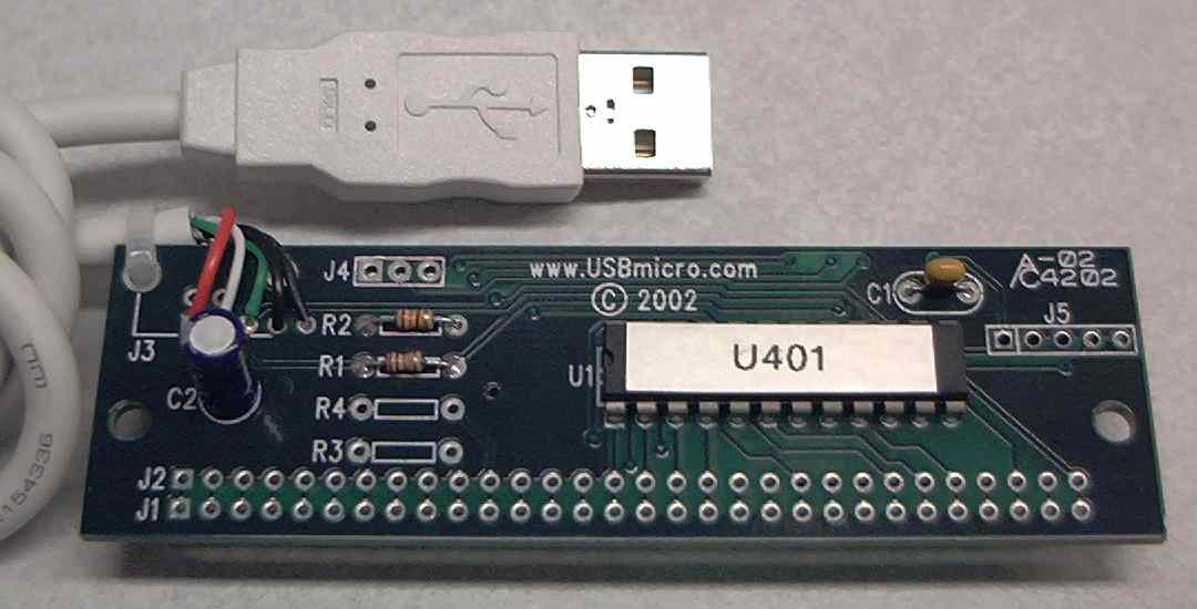
U401 front view, older style with DIP U401 chip
The next U401 devices are populated with a surface mount technology (SMT) microcontroller, as pictured below.
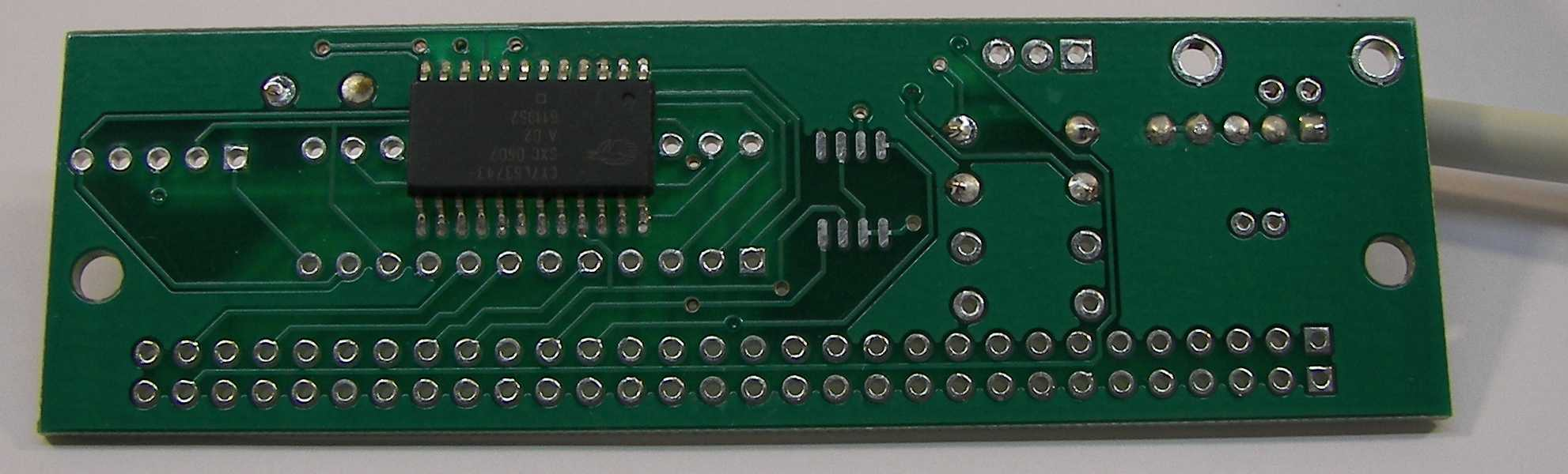
U401 back view, newer style with SMT U401 chip
The newest U401 devices.
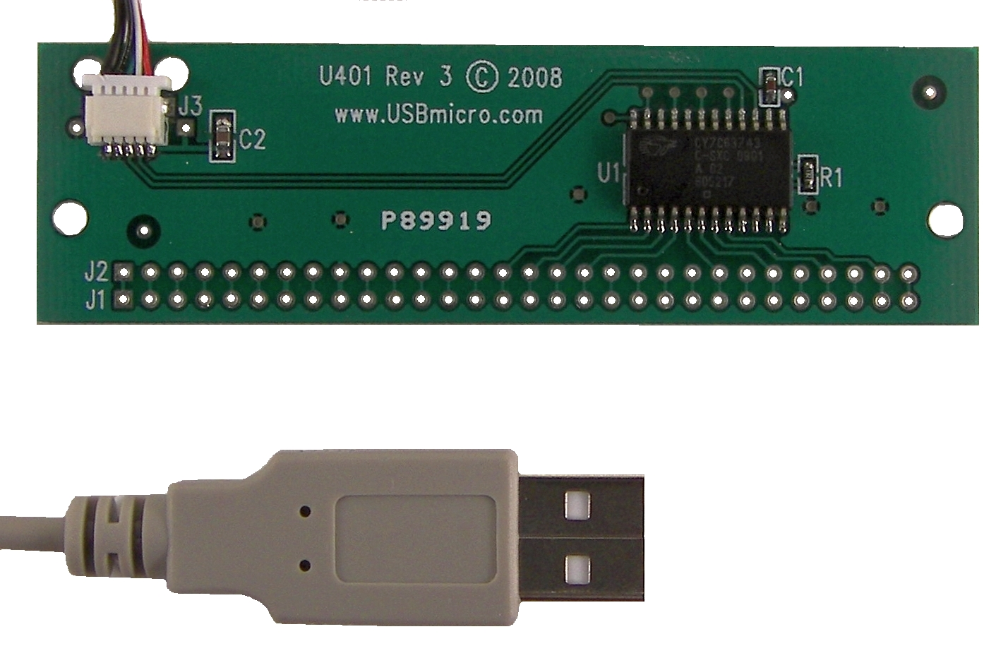
Newest U401 (Rev 3) front view. This newest U401 has a lightweight and removable USB cable.
Only one of these types is needed. All new U401 devices use the SMT microcontroller, so no DIP package will be on the front.
All U401, U421, and U451 devices are tested prior to shipping.
Leave a Reply