“DIP-like” Connector:
| Pin Number | U421 Signal |
| 1 | PA.0 – Port A bit 0 (stepper motor control) |
| 2 | PA.1 – Port A bit 1 (stepper motor control) |
| 3 | PA.2 – Port A bit 2 (stepper motor control) (2-wire clock) |
| 4 | PA.3 – Port A bit 3 (stepper motor control) (2 wire data) |
| 5 | PB.0 – Port B bit 0 |
| 6 | PB.2 – Port B bit 2 |
| 7 | PB.4 – Port B bit 4 |
| 8 | PB.6 – Port B bit 6 |
| 9 | Ground |
| 10 | No Connect |
| 11 | No Connect |
| 12 | Do not use |
| 13 | No Connect |
| 14 | +5V (USB) |
| 15 | USB D- (already connected to the USB cable) |
| 16 | USB D+ (already connected to the USB cable) |
| 17 | PB.7 – Port B bit 7 |
| 18 | PB.5 – Port B bit 5 |
| 19 | PB.3 – Port B bit 3 |
| 20 | PB.1 – Port B bit 1 |
| 21 | PA.7 – Port A bit 7 (or SPI SCK) (stepper motor control) |
| 22 | PA.6 – Port A bit 6 (or SPI MISO) (stepper motor control) |
| 23 | PA.5 – Port A bit 5 (or SPI MOSI) (stepper motor control) |
| 24 | PA.4 – Port A bit 4 (or SPI SS [when in slave mode]) (stepper motor control) |
Other Connectors:
There is a 2×6 pad layout on the board that can be used for connection to an AVR (such as an ATtiny) for programming. The 1×2 jumper applies 5V to this header. (Newest U421 board does not have this jumper – the 5V is on the 2×6 header.) The AVR programmer header follows that of the standard 2×6 AVR programming connector. Connections must be made on the component pads to allow signals out to this header.
Power Connection:
The +5V available on pin 14 is the power from the computer’s USB port. Up to 100mA can be drawn from this supply to power devices attached to the U421. If more power is needed, an external supply should be used to power additional circuits. Do not attach the +5V from an external supply to this pin. The ground connection should be common to any external power supply ground as well as any target circuits.
Board Layout:
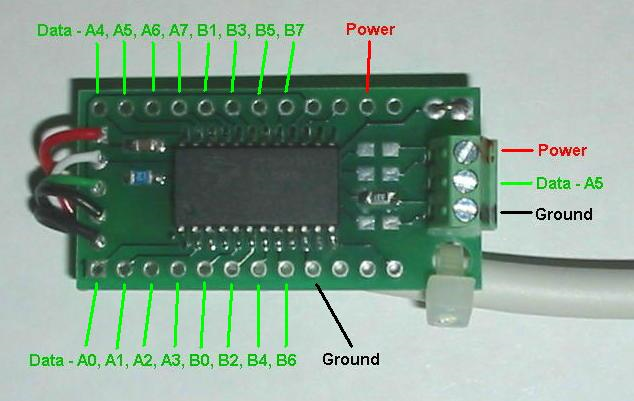
(U421-SC3 screw terminal version of the U421 no longer available) A standard U421 does not have the screw terminal.
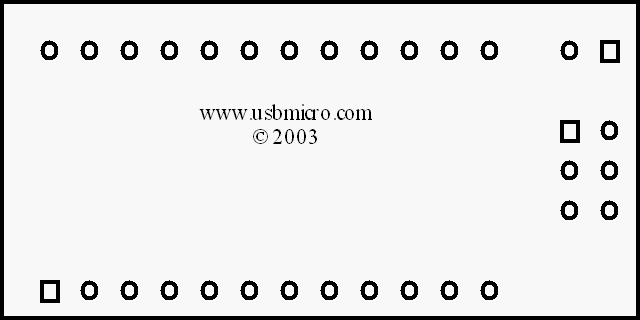
Pin 1 on the U421 is located on the lower left, as you look at the board in the orientation above. Pin 24 is the pin on the upper left. The lower row, therefore, is 1-12, the upper row is 24-13.