Relay 1 Connector:
| Pin Name | Description |
| N.C. | Normally Closed. When relay 1 is not activated, the common terminal connects to N.C. Relay 1 is Port B bit 0. |
| COM | Common. This connects to N.C. when relay 1 is not energized, and switches to N.O. when it is. |
| N.O. | Normally Open. When relay 1 is activated, the common terminal connects to N.O. |
Relay 2 Connector:
| Pin Name | Description |
| N.C. | Normally Closed. When relay 2 is not activated, the common terminal connects to N.C. Relay 1 is Port B bit 1 |
| COM | Common. This connects to N.C. when relay 2 is not energized, and switches to N.O. when it is. |
| N.O. | Normally Open. When relay 2 is activated, the common terminal connects to N.O. |
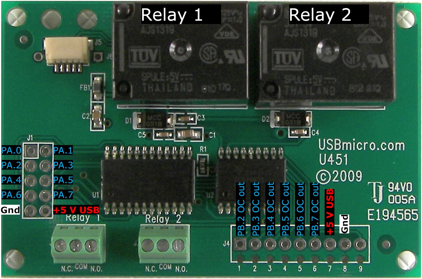
J4 Connector:
| Pin Number | Signal |
| 1 | PB.2 – Port B bit 2 driving a Darlington transistor to ground (a high sent to this port line pulls the pin to ground) |
| 2 | PB.3 – Port B bit 3 driving a Darlington transistor to ground (a high sent to this port line pulls the pin to ground) |
| 3 | PB.4 – Port B bit 4 driving a Darlington transistor to ground (a high sent to this port line pulls the pin to ground) |
| 4 | PB.5 – Port B bit 5 driving a Darlington transistor to ground (a high sent to this port line pulls the pin to ground) |
| 5 | PB.6 – Port B bit 6 driving a Darlington transistor to ground (a high sent to this port line pulls the pin to ground) |
| 6 | PB.7 – Port B bit 7 driving a Darlington transistor to ground (a high sent to this port line pulls the pin to ground) |
| 7 | +5V (USB) |
| 8 | Ground |
| 9 | Common for Darlington. Optionally connect to external voltage. |
J1 Connector:
| Pin Number | Signal |
| 1 | PA.0 – Port A bit 0 (stepper motor control) |
| 2 | PA.1 – Port A bit 1 (stepper motor control) |
| 3 | PA.2 – Port A bit 2 (stepper motor control) (2-wire clock) |
| 4 | PA.3 – Port A bit 3 (stepper motor control) (2-wire data) |
| 5 | PA.4 – Port A bit 4 (or SPI SS when in slave mode ) (stepper motor control) |
| 6 | PA.5 – Port A bit 5 (or SPI MOSI) (stepper motor control) |
| 7 | PA.6 – Port A bit 6 (or SPI MISO) (stepper motor control) |
| 8 | PA.7 – Port A bit 7 (or SPI SCK) (stepper motor control) |
| 9 | Ground |
| 10 | +5V (USB) |
Power Connection:
The +5V available is the power from the computer’s USB port. Up to 100mA can be drawn from this supply to power devices attached to the U451. If more power is needed, an external supply should be used to power additional circuits. Do not attach the +5V from an external supply to this pin. The ground connection should be common to any external power supply ground as well as any target circuits.
Relay Activation:
The two port lines that connect to the relays need to be set to output. PB.0 activates relay 1 when set to high, and PB.1 activates relay 2 when set to a high.
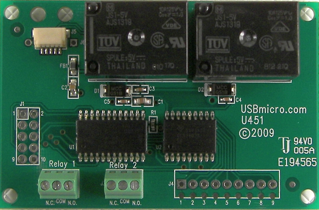
Board Layout: