Main Connector:
Along the long edge of the board is the SimmBus compatible connector, “J1”. “J2” is immediately next to J1, and is connected one-to-one electrically.
| Pin Number | SimmStick Signal | SimmStick Signal Description | U401 Signal |
| 1 | A1 | Special IO | <nc> (Pin 1 is located next to the silk screen “J1”.) |
| 2 | A2 | Special IO | <nc> |
| 3 | A3 | Special IO | <nc> |
| 4 | PWR | Unregulated DC 7.5 to 18V |
<nc> |
| 5 | A4 | Special IO | <nc> |
| 6 | A5 | Special IO | <nc> |
| 7 | +5V | +5V | +5V USB from PC |
| 8 | RES | Reset (Active low) | <nc> |
| 9 | GND | Ground | GND |
| 10 | SCL | I2C Clock | optional pull-up |
| 11 | SDA | I2C Data | optional pull-up |
| 12 | SI | Serial In | <nc> |
| 13 | SO | Serial Out | <nc> |
| 14 | A6 | Special IO | <nc> |
| 15 | D0 | General Purpose IO | PA.0 – Port A bit 0 (stepper motor control) |
| 16 | D1 | General Purpose IO | PA.1 – Port A bit 1 (stepper motor control) |
| 17 | D2 | General Purpose IO | PA.2 – Port A bit 2 (stepper motor control) (2-wire clock) |
| 18 | D3 | General Purpose IO | PA.3 – Port A bit 3 (stepper motor control) (2-wire data) |
| 19 | D4 | General Purpose IO (SS in slave mode) |
PA.4 – Port A bit 4 (stepper motor control) |
| 20 | D5 | General Purpose IO SPI MOSI |
PA.5 – Port A bit 5 (stepper motor control) |
| 21 | D6 | General Purpose IO SPI MISO |
PA.6 – Port A bit 6 (stepper motor control) |
| 22 | D7 | General Purpose IO SPI SCK |
PA.7 – Port A bit 7 (stepper motor control) |
| 23 | D8 | General Purpose IO | PB.0 – Port B bit 0 |
| 24 | D9 | General Purpose IO | PB.1 – Port B bit 1 |
| 25 | D10 | General Purpose IO | PB.2 – Port B bit 2 |
| 26 | D11 | General Purpose IO | PB.3 – Port B bit 3 |
| 27 | D12 | General Purpose IO | PB.4 – Port B bit 4 |
| 28 | D13 | General Purpose IO | PB.5 – Port B bit 5 |
| 29 | D14 | General Purpose IO | PB.6 – Port B bit 6 |
| 30 | D15 | General Purpose IO | PB.7 – Port B bit 7 |
Other Connectors:
J3 is the USB connection. J4 and J5 are for factory use.
Power Connection:
The +5V available on pin 7 of the SimmBus is the power from the computer’s USB port. Up to 100mA can be drawn from this supply to power devices attached to the U401. If more power is needed, an external supply should be used to power additional circuits. Do not attach the +5V from an external supply to this pin. The ground connection of the SimmBus should be common to any external power supply ground as well as any target circuits.
SimBus I2C Connection:
The pins labeled “SCL” and “SDA” are the SimBus I2C connections. On the U401 the connections are not made to the microcontroller. There are two unpopulated PCB positions for pull-up resistors for these lines. The I2C communication interface relies on a passive pull-up and an active pull-down. The positions can be populated with resistors if no other pull-up resistors exist on the SimmBus I2C lines.
Board Layout:
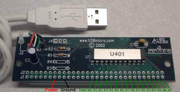
Please see the FAQ for information about the components used in the picture.
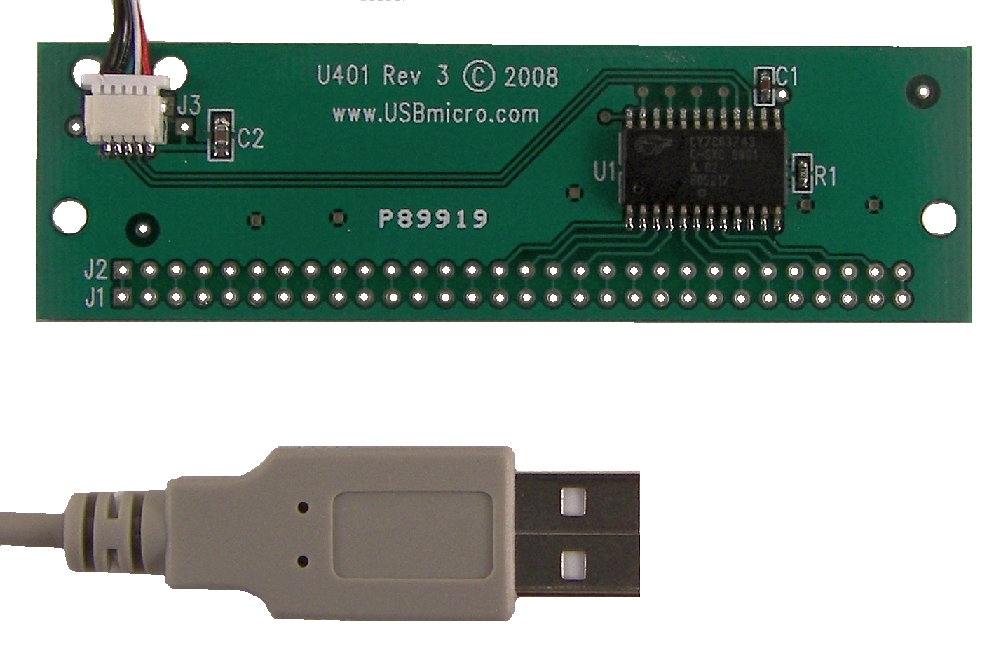
Newest U401 (Rev 3) front view. This newest U401 has a lightweight and removable USB cable.
Note that all lines extend from J1 to J2. There are then some J1 lines that only connect to J2 and no other circuitry.
Pin 1 on the U401 is located on the left, as you look at the board in the orientation above. Pin 30 is the pin on the far right.